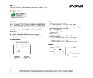
5-W00E 7.62 0.3 (0.3) 7.3 0.5 (0.287) LEAD FREE A 4N35 Y Y WW 3.5 0.5 (0.138) 6.5 0.5 (0.256) ANODE 6.9 0.5 (0.272) 2.8 0.5 (0.110) DATE CODE 2.3 0.5 (0.09) 2.54 0.25 (0.1) 0.5 0.1 (0.02) 0.26 (0.010) 10.16 0.5 (0.4) DIMENSIONS IN MILLIMETERS AND (INCHES) 4N35-300E 7.62 0.3 (0.3) 7.3 0.5 (0.287) LEAD FREE A 4N35 Y Y WW 3.5 0.5 (0.138) 6.5 0.5 (0.256) 0.35 0.25 (0.014) ANODE 1.2 0.1 (0.047) DATE CODE DIMENSIONS IN MILLIMETERS AND (INCHES) 2.54 0.25 (0.1) 1.0 0.25 (0.39) 10.16 0.3 (0.4) 0.26 (0.010) Solder Reflow Temperature Profile 2) When using another soldering method such as infrared ray lamp, the temperature may rise partially in the mold of the device. Keep the temperature on the package of the device within the condition of (1) above. 250C Temperature (C) 1) One-time soldering reflow is recommended within the condition of temperature and time profile shown at right. 30 seconds 217C 200C 150C 60 sec 25C 60 ~ 150 sec 90 sec Time (sec) Note: Non-halide flux should be used. Absolute Maximum Rati
 8 Pages, 219 KB, Original
st No. Order Code 4N25-000E 4N25-060E 124-4499 124-4500 124-4501 124-4502 4N25-300E 4N25-360E AV Input Current mA 10 10 10 CTR @10mA min. 100% 100% 100% 250+ 0.240 0.134 0.162 0.200 0.210 0.121 0.143 0.175 0.178 0.101 0.119 0.156 Mftrs. List No. 4N35-000E 4N35-300E** 4N35-W00E Package DIP-6 DIP-6 DIP-6 Order Code 163-4734 163-4735 163-4736 Price Each List No. Order Code 1+ 25+ 100+ 250+ 4N35-000E 4N35-300E 4N35-W00E 163-4734 163-4735 163-4736 0.250 0.250 0.250 0.174 0.181 0.180 0.146 0.154 0.153 0.129 0.140 0.139 High VCE I DIL Package with wide lead (0.4") options I CSA approved, with IEC/EN/DIN option (CNY17-3-W60E) I Good response time Av Output Current mA 150 Av Input Current mA 60 CTR min,max 100, 200 VISO V 5000 tF, tR s 5, 5 The CNY17 series contains a LED and phototransistor configuration. 453870 Mftrs. Pin config. Price Each Order Code 1+ 25+ 100+ 250+ Standard CNY17-3-000E 0.4" lead spacing CNY17-3-W00E List No. 124-4519 124-4523 0.4" lead spacing CNY17-3-W60E 124-4524 0.29
 232 Pages, 72548 KB, Original
ra-fast rectifier (SMA) Diodes Inc. US1K-TP D4 1 200V, 6A ultra-fast recovery rectifier (5 PowerDI) Diodes Inc. PDU620-13 D5 1 0I Q5% resistor (1206) L1 1 6.8mH, 0.8A line filter (13mm x 10mm) Wurth Elektronik 7448640401 U2 1 Phototransistor (6 DIP) Avago 4N35-300E 1 1 800V, 11A n-channel MOSFET (D2PAK) ST Micro STB11NM80T4 U3 1.24V, 0.5% shunt regulator (3 SOT23) Diodes Inc. TLV431BFTA -- 1 R1 1 10I, 2A NTC thermistor (5mm) EPCOS B57153S0100M000 PCB: MAX17595 EVALUATION KIT R2-R4 3 549kI Q1% resistors (1206) R5 1 19.8kI Q1% resistor (0603) N1 SUPPLIER *EP = Exposed pad. Component Suppliers PHONE WEBSITE Coilcraft, Inc. 847-639-6400 www.coilcraft.com Diodes Incorporated 805-446-4800 www.diodes.com EPCOS AG 732-906-4300 www.epcos.com Murata Electronics North America, Inc. 770-436-1300 www.murata-northamerica.com Panasonic Corp. 800-344-2112 www.panasonic.com STMicroelectronics 408-452-8585 www.us.st.com TDK Corp. 847-803-6100 www.component.tdk.com Note: Indicate that you are using the MAX17595ATE+
 9 Pages, 249 KB, Original
00E 7.62 0.3 (0.3) 7.3 0.5 (0.287) LEAD FREE A 4N35 3.5 0.5 (0.138) 6.5 0.5 (0.256) 6.9 0.5 (0.272) Y Y WW ANODE 2.8 0.5 (0.110) DATE CODE *1 2.3 0.5 (0.09) 2.54 0.25 (0.1) 0.5 0.1 (0.02) 0.26 (0.010) 10.16 0.5 (0.4) DIMENSIONS IN MILLIMETERS AND (INCHES) 4N35-300E 7.62 0.3 (0.3) 7.3 0.5 (0.287) LEAD FREE A 4N35 3.5 0.5 (0.138) 6.5 0.5 (0.256) 0.35 0.25 (0.014) Y Y WW ANODE 1.2 0.1 (0.047) DATE CODE *1 DIMENSIONS IN MILLIMETERS AND (INCHES) 2 2.54 0.25 (0.1) 1.0 0.25 (0.39) 10.16 0.3 (0.4) 0.26 (0.010) 2) When using another soldering method such as infrared ray lamp, the temperature may rise partially in the mold of the device. Keep the temperature on the package of the device within the condition of (1) above. 30 seconds 250C Temperature (C) Solder Reflow Temperature Profile 1) One-time soldering reflow is recommended within the condition of temperature and time profile shown at right. 217C 200C 150C 60 sec 25C 60 ~ 150 sec 90 sec Time (sec) Absolute Maximum Ratings Storage Temperature, TS Opera
 6 Pages, 73 KB, Original
00E 7.62 0.3 (0.3) 7.3 0.5 (0.287) LEAD FREE A 4N35 3.5 0.5 (0.138) 6.5 0.5 (0.256) 6.9 0.5 (0.272) Y Y WW ANODE 2.8 0.5 (0.110) DATE CODE *1 2.3 0.5 (0.09) 2.54 0.25 (0.1) 0.5 0.1 (0.02) 0.26 (0.010) 10.16 0.5 (0.4) DIMENSIONS IN MILLIMETERS AND (INCHES) 4N35-300E 7.62 0.3 (0.3) 7.3 0.5 (0.287) LEAD FREE A 4N35 3.5 0.5 (0.138) 6.5 0.5 (0.256) 0.35 0.25 (0.014) Y Y WW ANODE 1.2 0.1 (0.047) DATE CODE *1 DIMENSIONS IN MILLIMETERS AND (INCHES) 2 2.54 0.25 (0.1) 1.0 0.25 (0.39) 10.16 0.3 (0.4) 0.26 (0.010) 2) When using another soldering method such as infrared ray lamp, the temperature may rise partially in the mold of the device. Keep the temperature on the package of the device within the condition of (1) above. 30 seconds 250C Temperature (C) Solder Reflow Temperature Profile 1) One-time soldering reflow is recommended within the condition of temperature and time profile shown at right. 217C 200C 150C 60 sec 25C 60 ~ 150 sec 90 sec Time (sec) Absolute Maximum Ratings Storage Temperature, TS Opera
 6 Pages, 405 KB, Original
5-W00E 7.62 0.3 (0.3) 7.3 0.5 (0.287) LEAD FREE A 4N35 Y Y WW 3.5 0.5 (0.138) 6.5 0.5 (0.256) ANODE 6.9 0.5 (0.272) 2.8 0.5 (0.110) DATE CODE 2.3 0.5 (0.09) 2.54 0.25 (0.1) 0.5 0.1 (0.02) 0.26 (0.010) 10.16 0.5 (0.4) DIMENSIONS IN MILLIMETERS AND (INCHES) 4N35-300E 7.62 0.3 (0.3) 7.3 0.5 (0.287) LEAD FREE A 4N35 Y Y WW 3.5 0.5 (0.138) 6.5 0.5 (0.256) 0.35 0.25 (0.014) ANODE 1.2 0.1 (0.047) DATE CODE DIMENSIONS IN MILLIMETERS AND (INCHES) 2.54 0.25 (0.1) 1.0 0.25 (0.39) 10.16 0.3 (0.4) 0.26 (0.010) Solder Reflow Temperature Profile 2) When using another soldering method such as infrared ray lamp, the temperature may rise partially in the mold of the device. Keep the temperature on the package of the device within the condition of (1) above. 250C Temperature (C) 1) One-time soldering reflow is recommended within the condition of temperature and time profile shown at right. 30 seconds 217C 200C 150C 60 sec 25C 60 ~ 150 sec 90 sec Time (sec) Note: Non-halide flux should be used. Absolute Maximum Rati
 7 Pages, 221 KB, Original
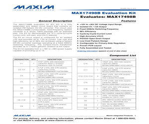
I Q1% resistor (0603) DESCRIPTION R20 1 30.1kI Q1% resistor (0603) T1 1 30W transformer (1:2:4) Coilcraft MA5237-AL U1 1 Offline 500kHz peak current-mode controller (16 TQFN-EP*) Maxim MAX17498BATE+ U2 1 Phototransistor/optocoupler (6 Dip Gull Wing) Avago 4N35-300E U3 1 1.24V shunt regulator (3 SOT23) Diodes Inc. TLV431BFTA -- 1 PCB: MAX17498B EVALUATION KIT *EP = Exposed pad. Component Suppliers SUPPLIER PHONE WEBSITE Coilcraft, Inc. 847-639-6400 www.coilcraft.com Diodes Incorporated 805-446-4800 www.diodes.com Murata Electronics North America, Inc. 770-436-1300 www.murata-northamerica.com Panasonic Corp. 800-344-2112 www.panasonic.com TDK Corp 847-803-6100 www.component.tdk.com Note: Indicate that you are using the MAX17498B when contacting these component suppliers. Quick Start Required Equipment * MAX17498B EV kit * +18V to +36V power supply capable of providing up to 1A * Two voltmeters * Electronic load capable of sinking 1.5A Procedure The EV kit is fully assembled and tested. Follow the s
 8 Pages, 692 KB, Original
I Q1% resistor (0603) DESCRIPTION R20 1 30.1kI Q1% resistor (0603) T1 1 30W transformer (1:2:4) Coilcraft MA5237-AL U1 1 Offline 500kHz peak current-mode controller (16 TQFN-EP*) Maxim MAX17498BATE+ U2 1 Phototransistor/optocoupler (6 Dip Gull Wing) Avago 4N35-300E U3 1 1.24V shunt regulator (3 SOT23) Diodes Inc. TLV431BFTA -- 1 PCB: MAX17498B EVALUATION KIT *EP = Exposed pad. Component Suppliers SUPPLIER PHONE WEBSITE Coilcraft, Inc. 847-639-6400 www.coilcraft.com Diodes Incorporated 805-446-4800 www.diodes.com Murata Electronics North America, Inc. 770-436-1300 www.murata-northamerica.com Panasonic Corp. 800-344-2112 www.panasonic.com TDK Corp 847-803-6100 www.component.tdk.com Note: Indicate that you are using the MAX17498B when contacting these component suppliers. Quick Start Required Equipment * MAX17498B EV kit * +18V to +36V power supply capable of providing up to 1A * Two voltmeters * Electronic load capable of sinking 1.5A Procedure The EV kit is fully assembled and tested. Follow the s
 7 Pages, 704 KB, Original
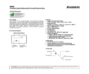
00E 7.62 0.3 (0.3) 7.3 0.5 (0.287) LEAD FREE A 4N35 3.5 0.5 (0.138) 6.5 0.5 (0.256) 6.9 0.5 (0.272) Y Y WW ANODE 2.8 0.5 (0.110) DATE CODE *1 2.3 0.5 (0.09) 2.54 0.25 (0.1) 0.5 0.1 (0.02) 0.26 (0.010) 10.16 0.5 (0.4) DIMENSIONS IN MILLIMETERS AND (INCHES) 4N35-300E 7.62 0.3 (0.3) 7.3 0.5 (0.287) LEAD FREE A 4N35 3.5 0.5 (0.138) 6.5 0.5 (0.256) 0.35 0.25 (0.014) Y Y WW ANODE 1.2 0.1 (0.047) DATE CODE *1 DIMENSIONS IN MILLIMETERS AND (INCHES) 3 2.54 0.25 (0.1) 1.0 0.25 (0.39) 10.16 0.3 (0.4) 0.26 (0.010) 2) When using another soldering method such as infrared ray lamp, the temperature may rise partially in the mold of the device. Keep the temperature on the package of the device within the condition of (1) above. 30 seconds 250C Temperature (C) Solder Reflow Temperature Profile 1) One-time soldering reflow is recommended within the condition of temperature and time profile shown at right. 217C 200C 150C 60 sec 25C 60 ~ 150 sec 90 sec Time (sec) Note: Non-halide flux should be used. Absolute Maximum
 7 Pages, 170 KB, Original


