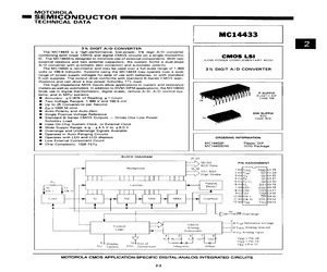
MC14433 3% DIGIT A/D CONVERTER The MC14433 is a high-performance, low-power, 3% digit A/D converter combining both linear CMOS and digital CMOS circuits on a single monolithic CMOS LSI IC. The MC14433 is designed to minimize use of external components. With two (LOW-POWER COMPLEMENTARY MOS) external resistors and two external capacitors, the system forms a dual-slope A/D converter with automatic zero correction and automatic polarity. The MC14433 is ratiometric and may be used over a full-scale range of 1.999 3% DIGIT A/D CONVERTER volts or 199.9 millivolts. Systems using the MC14433 may operate over a wide range of power supply voltages for ease of use with batteries, or with standard 5 valt supplies. The output drive conforms with standard B-Series CMOS spec- ifications and can drive a low-power Schottky TTL ioad. The high-impedance MOS inputs allow applications in current and resistance meters as well as voltmeters. In addition ta DVM/DPM app
 12 Pages, 493 KB, Scan
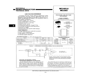
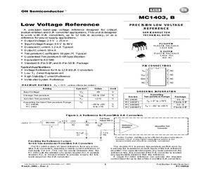
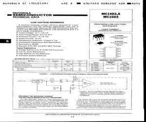
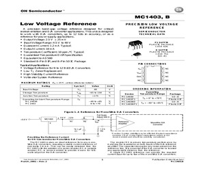
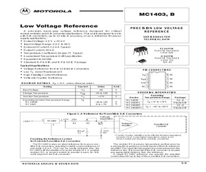
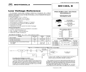
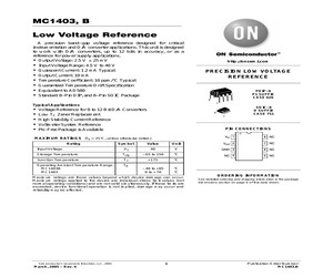
MC14433 A/D systems. Low temperature drift is a prime design consideration. @ Output Voltage: 2.5 V +25 mV @ Input Voltage Range: 4.5 V to 40 V @ Quiescent Current: 1.2 mA Typ @ Output Current: 10 mA Temperature Coefficient: 10 ppm/C Typ e Guaranteed Temperature Drift Specification @ Equivalent to AD580 @ Standard 8-Pin DIP, and 8-Pin SOIC Package Typical Applications @ Voltage Reference for 8-12 Bit D/A Converters @ Low Tc Zener Replacement @ High Stability Current Reference Voltmeter System Reference MAXIMUM RATINGS (Ta = 25C unless otherwise noted.) = SEMICONDUCQ yyy: MC1403,A MC1503 PRECISION LOW VOLTAGE REFERENCE LASER TRIMMED INTEGRATED CIRCUIT U SUFFIX CERAMIC PACKAGE 1 CASE 693 @ D SUFFIX PLASTIC PACKAGE CASE 751 1 (SO-8) Vintt Bike Vout [2| Ne Gna [3] ls] NC nc [a] [5] Nc ORDERING INFORMATION Rating Symbol Value Unit Temperature Input Voltage a 40 v Device Range Package Storage Temperature Tstg -65 to 150 C MC1503U 65 to +125C Ceramic DIP Junction Temperature Ty 4175 % MC1403D $0-8 Opera
 4 Pages, 107 KB, Scan
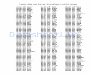
 Cur rent output, 300nS, 1/4 LSD Diff Linear i ty R ef, Hy b r id Current output, 3005, 1/4 LSD Diff L inearity R ef, Wi ll work /12 . supplies DAC80V 156-0959-00 8701 12-Bit 1 156-1571-00 One-chip D VM Systems I CL7106 156-1483-00 I CL7107 156-1435-00 M- MC14433 156-1118-00 Two-chip DVM L D110 24 D I P 4 40 D I P 3E 24 D I P 4 16 DIP 4G 16 D I P Systems 1156-0476-00 L LD111A 156-1268-00 L+ L D111A 156-1268-01 LD120 156-1306-00 L LD121 156-1305-00 L+ I CL8052 156-0909-00 I CL8053 156-0908-00 - 3-1/2 d i g it, Di gi tal section, 2 to 25 clock use with LD111A or L D120 3-1/2 d igit, Analog section, u se with LD110 3-1/2 d igit, Analog section, special noise select i on, u se with LD110 4-1/2 d igit, Analog sect i on, use with LD121 or L D110 4-1/2 d igit, Digital section, 50 to 250 z, u se with LD120 or L D111A 3-1/2 d ig i t, Analog signal conditioner, u se with I CL8053 or 71 3 3-1/2 d igit, Auto zero switch network, u se with I CL8052 3F 8-Bit DAC-08 156-1255-00 - DAC-08 156-1255-01 - AD558 15 -
 414 Pages, 31518 KB, Original
 drivers and resistors to drive the segments of the display. The digit drive is provided by four MPS-A12 Darlington transistors operating in an emitter-follower configuration. The MC14543B, MC14013B and LED displays are referenced to VEE via Pin 13 of the MC14433. This places the full power supply voltage across the display. The current for the display may be adjusted by the value of the segment resistors shown as 150 in Figure 8. An example of a 3-1/2-digit voltmeter using the MC14433 is shown in the circuit diagram of Figure 8. The reference voltage for the system uses an MC1403 2.5 V reference IC. The full scale potentiometer can calibrate for a full scale of 199.9 mV or 1.999 V. When switching from 2.0 V to 200 mV operation, RI is also changed, as shown on the diagram. When using RC equal to 300 k, the clock frequency for the system is about 66 kHz. The resulting conversion time is approximately 250 ms. When the input is overrange, the display flashes on and off. The flashing rat
 8 Pages, 90 KB, Original
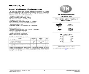
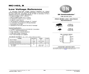
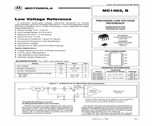
A MC1503 LOW VOLTAGE REFERENCE A precision band-gap voltage reference designed for critical instrumentation and D/A converter applications. This unit is designed to work with Motorola MC1508 and MC3510 D/A con- PRECISION LOW VOLTAGE REFERENCE verters, and MC14433 A/D systems. Low temperature drift is a LASER TRIMMED prime design consideration. Output Voltage: 2.5 V +25 mV Input Voltage Range: 4.5 V to 40 V @ Quiescent Current: 1.2 mA Typ @ Output Current: 10 mA Temperature Coefficient: 10 ppm/C Typ Guaranteed Temperature Drift Specification Equivalent to AD580 Standard 8-Pin DIP, and 8-Pin SOIC Package Typical Applications @ Voltage Reference for 8-12 Bit D/A Converters @ Low Tc Zener Replacement @ High Stability Current Reference @ Voltmeter System Reference MAXIMUM RATINGS (T, = 25C unless atherwise noted.) INTEGRATED CIRCUIT U SUFFIX CERAMIC PACKAGE CASE 693 D SUFFIX PLASTIC PACKAGE CASE 751 1 (SO-8) [+] [e] ne Vout [2] NC Gnd [6] Nc ne [a] [5] Nc < 3 ORDERING INFORMATION PROVIDING THE REFEREN
 4 Pages, 209 KB, Scan
 drivers and resistors to drive the segments of the display. The digit drive is provided by four MPS-A12 Darlington transistors operating in an emitter-follower configuration. The MC14543B, MC14013B and LED displays are referenced to VEE via Pin 13 of the MC14433. This places the full power supply voltage across the display. The current for the display may be adjusted by the value of the segment resistors shown as 150 in Figure 8. 3-1/2-Digit Voltmeter - Common Anode Displays, Flashing Overrange An example of a 3-1/2-digit voltmeter using the MC14433 is shown in the circuit diagram of Figure 8. The reference voltage for the system uses an MC1403 2.5 V reference IC. The full scale potentiometer can calibrate for a full scale of 199.9 mV or 1.999 V. When switching from 2.0 V to 200 mV operation, RI is also changed, as shown on the diagram. When using RC equal to 300 k, the clock frequency for the system is about 66 kHz. The resulting conversion time is approximately 250 ms. When the in
 2677 Pages, 35109 KB, Original
 drivers and resistors to drive the segments of the display. The digit drive is provided by four MPS-A12 Darlington transistors operating in an emitter-follower configuration. The MC14543B, MC14013B and LED displays are referenced to VEE via Pin 13 of the MC14433. This places the full power supply voltage across the display. The current for the display may be adjusted by the value of the segment resistors shown as 150 in Figure 8. An example of a 3-1/2-digit voltmeter using the MC14433 is shown in the circuit diagram of Figure 8. The reference voltage for the system uses an MC1403 2.5 V reference IC. The full scale potentiometer can calibrate for a full scale of 199.9 mV or 1.999 V. When switching from 2.0 V to 200 mV operation, RI is also changed, as shown on the diagram. When using RC equal to 300 k, the clock frequency for the system is about 66 kHz. The resulting conversion time is approximately 250 ms. When the input is overrange, the display flashes on and off. The flashing rat
 8 Pages, 86 KB, Original
 drivers and resistors to drive the segments of the display. The digit drive is provided by four MPS-A12 Darlington transistors operating in an emitter-follower configuration. The MC14543B, MC14013B and LED displays are referenced to VEE via Pin 13 of the MC14433. This places the full power supply voltage across the display. The current for the display may be adjusted by the value of the segment resistors shown as 150 in Figure 8. 3-1/2-Digit Voltmeter - Common Anode Displays, Flashing Overrange An example of a 3-1/2-digit voltmeter using the MC14433 is shown in the circuit diagram of Figure 8. The reference voltage for the system uses an MC1403 2.5 V reference IC. The full scale potentiometer can calibrate for a full scale of 199.9 mV or 1.999 V. When switching from 2.0 V to 200 mV operation, RI is also changed, as shown on the diagram. When using RC equal to 300 k, the clock frequency for the system is about 66 kHz. The resulting conversion time is approximately 250 ms. When the in
 43 Pages, 931 KB, Original
 drivers and resistors to drive the segments of the display. The digit drive is provided by four MPS-A12 Darlington transistors operating in an emitter-follower configuration. The MC14543B, MC14013B and LED displays are referenced to VEE via Pin 13 of the MC14433. This places the full power supply voltage across the display. The current for the display may be adjusted by the value of the segment resistors shown as 150 in Figure 8. 3-1/2-Digit Voltmeter - Common Anode Displays, Flashing Overrange An example of a 3-1/2-digit voltmeter using the MC14433 is shown in the circuit diagram of Figure 8. The reference voltage for the system uses an MC1403 2.5 V reference IC. The full scale potentiometer can calibrate for a full scale of 199.9 mV or 1.999 V. When switching from 2.0 V to 200 mV operation, RI is also changed, as shown on the diagram. When using RC equal to 300 k, the clock frequency for the system is about 66 kHz. The resulting conversion time is approximately 250 ms. When the in
 8 Pages, 89 KB, Original
 drivers and resistors to drive the segments of the display. The digit drive is provided by four MPS-A12 Darlington transistors operating in an emitter-follower configuration. The MC14543B, MC14013B and LED displays are referenced to VEE via Pin 13 of the MC14433. This places the full power supply voltage across the display. The current for the display may be adjusted by the value of the segment resistors shown as 150 in Figure 8. An example of a 3-1/2-digit voltmeter using the MC14433 is shown in the circuit diagram of Figure 8. The reference voltage for the system uses an MC1403 2.5 V reference IC. The full scale potentiometer can calibrate for a full scale of 199.9 mV or 1.999 V. When switching from 2.0 V to 200 mV operation, RI is also changed, as shown on the diagram. When using RC equal to 300 k, the clock frequency for the system is about 66 kHz. The resulting conversion time is approximately 250 ms. When the input is overrange, the display flashes on and off. The flashing rat
 8 Pages, 90 KB, Original
 drivers and resistors to drive the segments of the display. The digit drive is provided by four MPS-A12 Darlington transistors operating in an emitter-follower configuration. The MC14543B, MC14013B and LED displays are referenced to VEE via Pin 13 of the MC14433. This places the full power supply voltage across the display. The current for the display may be adjusted by the value of the segment resistors shown as 150 in Figure 8. An example of a 3-1/2-digit voltmeter using the MC14433 is shown in the circuit diagram of Figure 8. The reference voltage for the system uses an MC1403 2.5 V reference IC. The full scale potentiometer can calibrate for a full scale of 199.9 mV or 1.999 V. When switching from 2.0 V to 200 mV operation, RI is also changed, as shown on the diagram. When using RC equal to 300 k, the clock frequency for the system is about 66 kHz. The resulting conversion time is approximately 250 ms. When the input is overrange, the display flashes on and off. The flashing rat
 6 Pages, 82 KB, Original
406 03714 03285 02180 02237 03793 01698 02910 01698 034o6 01921 03794 Desc. TLO84CN Mc14536Bcp LM393N HA2-2605-5 LHOO7o-2H SD5000B LF13331D LF13333D LM32OT-12 LM3909N MC1458SP1 AD536AJD LF298H LM317K MC3405P HA2-2655-5 AM68TADL SG35241 HIl-1818A-5 AD559KD MC14433L ICL 8049 CC PE LF356EN LM341P-8 .0 LM341P-12 LM341P-24 MC1495L LM340LAH-12 LH-0053CG OP-OICJ UA79GUIC UATBGKC UA79GHC UA7905uc ICL8052CPD LF257H LM320T-8 .0 TL497CN UA7915KC LD130CJ DAC-lOOACQ3 NE527N UA78GUIC LM325H LF255H LH0042CD UA78L26AWC MC3410CL MC78M15CT cA314OT MC1403p1 MC3423PI AF120CH OP-07CJ SELECTED LH0044ACH MC3467P MC3468P TL601CP TL610CP LM7go6T LF13333N LH0033CC RA2- 2525 -5 UA79MGUIC UA78MCUIC AD7530LN MC14052BCP HA2-2625-5 (SELECTED) LM218H IH5028CPE LF355N DS3630N LM30BAN MCT9Ll2ACG MC79LO5ACG LF311H LH0091CD AD536AKD Mcl4053BCP Mc14o66Bcp LF398H AD?530LD CA3140E SZA266 AD561JD MC1658P LF13332N UA79M15AHC UA78M15HC LM310H SELECTED OP-17FJ ADCOBOOPCD TL071CP TL071BCP TL072CP TL074CN LM33TK LM324AN MC3420P LM33TT LF356
 143 Pages, 17060 KB, Original
 drivers and resistors to drive the segments of the display. The digit drive is provided by four MPS-A12 Darlington transistors operating in an emitter-follower configuration. The MC14543B, MC14013B and LED displays are referenced to VEE via Pin 13 of the MC14433. This places the full power supply voltage across the display. The current for the display may be adjusted by the value of the segment resistors shown as 150 in Figure 8. An example of a 3-1/2-digit voltmeter using the MC14433 is shown in the circuit diagram of Figure 8. The reference voltage for the system uses an MC1403 2.5 V reference IC. The full scale potentiometer can calibrate for a full scale of 199.9 mV or 1.999 V. When switching from 2.0 V to 200 mV operation, RI is also changed, as shown on the diagram. When using RC equal to 300 k, the clock frequency for the system is about 66 kHz. The resulting conversion time is approximately 250 ms. When the input is overrange, the display flashes on and off. The flashing rat
 8 Pages, 80 KB, Original
 drivers and resistors to drive the segments of the display. The digit drive is provided by four MPS-A12 Darlington transistors operating in an emitter-follower configuration. The MC14543B, MC14013B and LED displays are referenced to VEE via Pin 13 of the MC14433. This places the full power supply voltage across the display. The current for the display may be adjusted by the value of the segment resistors shown as 150 in Figure 8. 3-1/2-Digit Voltmeter - Common Anode Displays, Flashing Overrange An example of a 3-1/2-digit voltmeter using the MC14433 is shown in the circuit diagram of Figure 8. The reference voltage for the system uses an MC1403 2.5 V reference IC. The full scale potentiometer can calibrate for a full scale of 199.9 mV or 1.999 V. When switching from 2.0 V to 200 mV operation, RI is also changed, as shown on the diagram. When using RC equal to 300 k, the clock frequency for the system is about 66 kHz. The resulting conversion time is approximately 250 ms. When the in
 8 Pages, 87 KB, Original
Vout (mV) do A Oo Oo -10 2 -40 -30 -20 -10 0 10 20 30 40 50 Ta, TEMPERATURE (C) lIo=OmA =8.0mA 60 70 8085 MOTOROLA ANALOG IC DEVICE DATAMC1403, B 31/2-Digit Voltmeter Common Anode Displays, Flashing Overrange An example of a 31/2-digit voltmeter using the MC14433 is shown in the circuit diagram of Figure 8. The reference voltage for the system uses an MC1403 2.5 V reference IC. The full scale potentiometer can calibrate for a full scale of 199.9 mV or 1.999 V. When switching from 2.0 V to 200 mV operation, R] is also changed, as shown on the diagram. When using Rc equal to 300 kQ, the clock frequency for the system is about 66 kHz. The resulting conversion time is approximately 250 ms. When the input is overrange, the display flashes on and off. The flashing rate is one-half the conversion rate. This is done by dividing the EOC pulse rate by 2 with 1/2 MC14013B flip-flop and blanking the display using the blanking input of the MC14543B. The display uses an LED display with common anode digit line
 5 Pages, 281 KB, Scan


